Principle and capacity of heat exchangers
- Capacity of heat exchangers
- Efficiency of plate heat exchangers
- Plate thickness and channel patterns (H, M or L)
- Circulation pumps
- Heat loss of the exchanger
- Connecting the ports
Customers typically require heat exchangers for applications without phase change – common examples include water-to-water heat exchangers for heating or oil-to-water coolers.
In some cases, the working fluid undergoes a phase transition within the heat exchanger:
- Evaporator – the refrigerant evaporates, transitioning from a liquid to a gaseous state.
- Condenser – the refrigerant condenses, changing from a gas to a liquid.
Plate heat exchanger capacity
Capacity is a key consideration for users, but the heat transfer capacity of a plate heat exchanger is not fixed for a given model. A single unit may handle 20 kW or 100 kW, depending on operating conditions. Several factors influence performance, including
- Heat exchanger dimensions (width, height)
- Number of plates
- Channel patterns
- Flow rates
- Temperature difference between primary and secondary circuits
- Physical properties of the fluids (e.g., viscosity, thermal conductivity, phase state)
Heat Exchanger Design Considerations
Plate heat exchangers are typically arranged in counterflow configuration, which significantly improves efficiency compared to cocurrent flow.
- Longer plates enhance heat transfer by allowing a greater temperature approach between the primary inlet and secondary outlet.
- Pressure losses increase with longer plates, requiring a more powerful pump to maintain flow.
- Adding more plates reduces pressure drop (doubling the number of plates reduces pressure losses to a quarter).

Heat exchanger efficiency
An ideal heat exchanger would achieve 100 % efficiency, but real systems always experience some losses. However, plate heat exchangers are among the most efficient types available, often exceeding 90 % efficiency. In practice, this means the cold-side fluid is heated to a higher temperature than it would be if the two media were simply mixed. This high efficiency is largely due to the countercurrent flow arrangement, which maximizes heat transfer.
To achieve high efficiency, a large heat exchange area is required. This is accomplished through:
- Stacked stainless steel plates (typically AISI 316, 0.5 mm thick).
- Corrugated surfaces that increase the heat transfer area and induce turbulence, enhancing performance and providing self-cleaning properties.
- Alternating hot and cold flow channels, ensuring the media remain separate while maximizing heat transfer.

Sealing Methods
- Brazed Plate Heat Exchangers – Use copper or nickel solder to seal the chambers, which also contributes to heat transfer.
- Gasketed Plate Heat Exchangers – Use rubber gaskets instead of solder, allowing them to be opened for cleaning or expanded by adding more plates.
Efficiency vs. Cost
When designing a heat exchanger, a balance between cost and efficiency is crucial. In many applications, extreme efficiency is unnecessary, as unused heat may simply return to the source. Additionally, achieving incremental efficiency gains becomes increasingly expensive.
Heat exchanger plates count
Increasing the number of plates enhances performance, but with diminishing returns—initial gains are significant, while further additions have a smaller effect. To maintain performance improvements, flow rates must also increase.
- Doubling both the number of plates and flow rates results in double the heat transfer capacity.
- Longer heat exchangers improve efficiency by allowing primary and secondary temperatures to approach each other more closely.
- Higher efficiency comes at the cost of greater pressure losses, which can be mitigated by adding more plates.
Alternative Efficiency Boost: Dual Exchangers
Efficiency can also be improved by placing two heat exchangers in series. However, this is only practical for low flow rates, as pressure losses increase. A more efficient solution is a single heat exchanger with four connections, encapsulating both circuits.
Plate Thickness and Thermal Conductivity
Plate thickness affects both efficiency and durability:
- Thinner plates improve heat transfer but reduce mechanical and chemical resistance.
- Thicker plates provide better durability but lower thermal conductivity.


Channel patterns

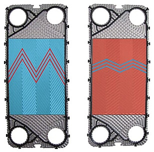
Most manufacturers offer heat exchangers with L, M, or H herringbone patterns, or combinations such as L + M or M + H. These patterns affect both efficiency and pressure loss:
- H-plates (High Theta, Large Angle) – Creates higher turbulence, leading to high efficiency but also higher pressure losses.
- M-plates (Medium Angle) – A balanced option between efficiency and resistance.
- L-plates (Low Theta, Small Angle) – Offers lower resistance but also lower efficiency.

Turbulent Flow & Pressure Loss Considerations
The suitability of a channel pattern depends on project calculations. Higher pressure losses increase the workload on the circulation pump. If losses are too high, adding more plates can help reduce resistance. However, excessive reduction in pressure loss is undesirable, as it weakens turbulent flow, lowering shear stress and increasing the risk of fouling. Turbulent flow prevents dirt buildup and occurs when:
- Reynolds number (R) > 150
- Shear stress > 35 Pa (ideally 50 Pa)
If fouling is a concern, the heat exchanger should not be oversized. Our calculation software can determine the most suitable channel pattern for your project.
Flow Rate & Heat Exchanger Performance
Adjusting the flow rate allows control over the exchanger’s output:
- Doubling the flow in both circuits doubles the heat transfer capacity.
- However, pressure losses increase with the square of the flow rate, making high flow rates impractical due to excessive pumping costs.
- In standard designs, flow rates of 1 to 3 m3/h with pressure losses around 20 kPa are typically optimal.


Improperly designed piping can result in significantly higher pressure losses than the in the heat exchanger itself. Key factors include:
- Fittings – Each additional fitting increases resistance. For instance, a single elbow adds pressure loss equivalent to 25 times the pipe diameter.
- Example Calculation – In a 1-inch pipe (Ø25 mm) with six elbows, the added equivalent length is: 6 × 25 × 25 = 3.8 meters.
- Alternative Solutions – Using bends instead of elbows can reduce pressure losses by nearly 50 %.
- Gradual Transitions – Abrupt diameter changes cause turbulence and additional losses; gradual transitions minimize this effect.
Heat Losses in Plate Heat Exchangers
SWEP plate heat exchangers have two circuits:
- Internal Circuit (Connections on the Left) – Usually the primary circuit, consisting only of inner plates.
- External Circuit (Connections on the Right) – Usually the secondary circuit, where the first and last plates act as end plates.
For higher efficiency, connect the hot medium to the internal circuit—this minimizes heat loss to the surroundings. Insulating the heat exchanger prevents heat loss and condensation buildup. Dedicated insulation is available for this purpose.
Heat Exchanger Calculations
Several other factors influence heat transfer capacity. For precise sizing, we recommend requesting a custom calculation. The following tools are available:
- Online Water/Water Heat Exchanger Calculator (also applicable for coolers)
- Online Oil/Water Plate Cooler Calculator
- SWEP BPHE Capacity Table (70/50 °C hot, 40/60 °C cold side)
- ARES Gasketed Heat Exchanger Capacity Table (90/80 °C hot, 75/85 °C cold side)
Connecting plate exchanger
General Installation Precautions
- Avoid excessive pulsations – Cyclic pressure or temperature fluctuations can damage the exchanger.
- Prevent freezing – Ensure the media inside the exchanger never freezes, as this can cause structural damage.
- Minimize vibrations – If vibrations are present, install vibration absorbers to protect the exchanger.
- Use control valves on inlets – At startup, slowly open the inlet valves while keeping the outlet fully open.
- Install drainage and venting – Drain valve at the lowest connection point. Vent valve at the highest connection point (must be opened during startup).
- Protect against overpressure – If system pressure might exceed the exchanger’s design pressure, install a pressure relief valve on the inlets.


Circuit Orientation & Positioning
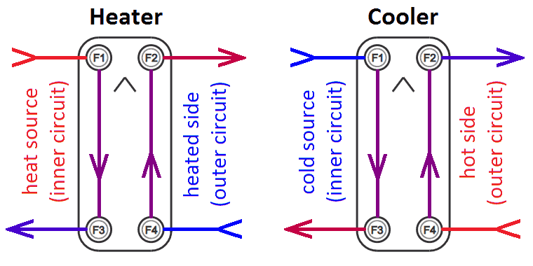
If the arrow points upward:
- Internal Circuit (left side when vertical) – Typically connected to the heat source or refrigerant.
- Outer Circuit (right side when vertical) – Uses end plates and is usually for the cold medium to minimize heat loss.
Heater can be installed vertically or horizontally with inlets at the top or bottom. Recommended connections (this setup reduces limescale buildup and prevents unnecessary heat loss): hot circuit enters F1, exits F3. Cold circuit: enters F4, exits F2. For asymmetric heat exchangers (e.g., E8ASH, E8LASH):
- The inner circuit (F1-F3) is narrower with higher pressure losses.
- In flow heaters, the heated DHW should be connected to the outer, wider circuit (F4-F2) for optimal performance.
Cooler – positioning and connections have little effect on operation. It can be placed vertically or horizontally. The outer circuit should be used for the hot medium, as heat will escape into the surrounding space.
Condenser – refrigerant must enter from the top, and condensate must drain from the bottom. If terminals F1 and F3 are identical, the exchanger can be rotated 180 degrees. For steam-to-water applications, refer to steam exchanger guidelines.
Evaporator – liquid refrigerant must enter at the bottom and evaporate, with vapors discharged at the top. Some models have F3 equipped with a distribution device for even refrigerant distribution. Refrigerant velocity guidelines for proper operation:
- Inlet speed: 10–25 m/s
- Outlet speed: 5–10 m/s (2.5–5 m/s for horizontal connections)
- Maintaining proper velocity prevents oil accumulation inside the heat exchanger.


For more details see
Pohraniční 1280/112
703 00 Ostrava-Vítkovice
Czech Republic
| L | +44 74 9187 2667 |
| E | +44 74 9187 2667 |
| B | info@heat-exchangers.uk |
| sales@heat-exchangers.uk |


