Heat exchanger for heat pump
- Condenser for heat pump
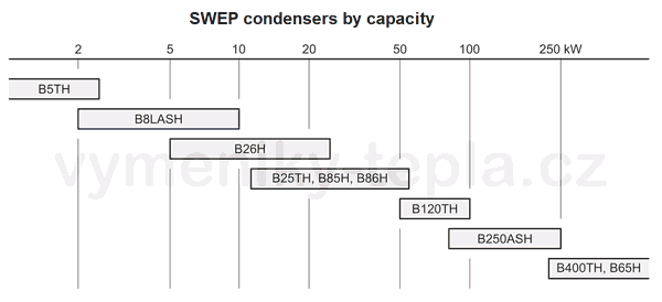
- Overview of condensers by heat load in kW
- The design pressures of the exchangers (in bars)
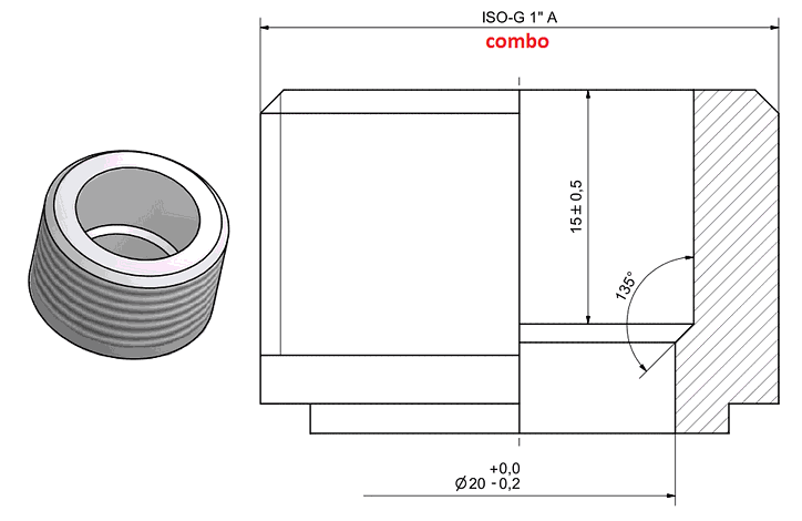
- Combo connections (i.e. both soldering and external threading)
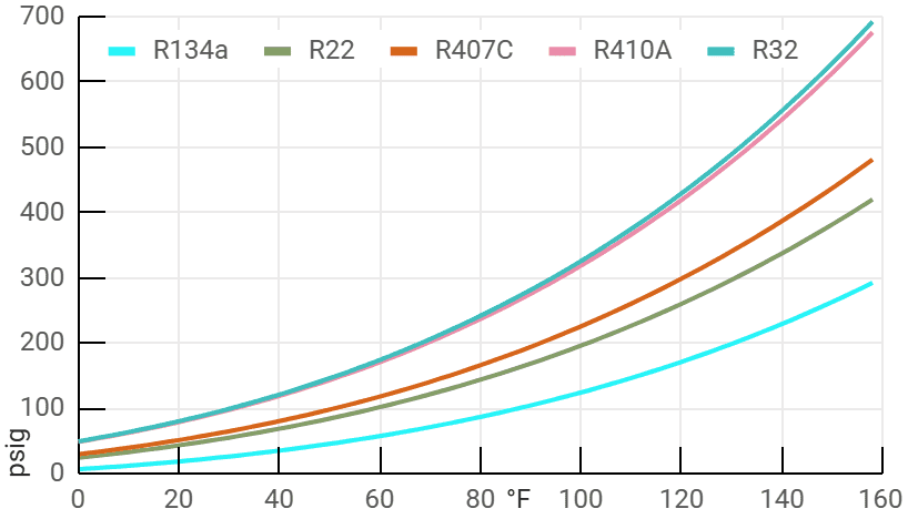
- Pressure-temperature charts
- Heat pump freezing, SWEP B26FH
- Evaporator for heat pump
- Separation exchanger
Converting an Air Conditioner into a Heat Pump
Is Conversion Right for You?
Advantages:
- Cost-Effective: Lower initial costs compared to purchasing a dedicated heat pump.
- Convenience: Ideal for users who already own an air conditioner or have the technical skills to perform the conversion themselves.
Disadvantages:
- Reduced Efficiency: Converted systems typically operate less efficiently than purpose-built heat pumps.
- Non-Optimized Components: Standard air conditioner components are not designed for optimal heating performance.
Popular Brands: Brands such as Sinclair Split, LG, Mitsubishi, Panasonic, Carrier Comfort, Trane, and Lennox Elite offer systems where many components are shared between air conditioners and heat pumps, making them suitable for conversion.
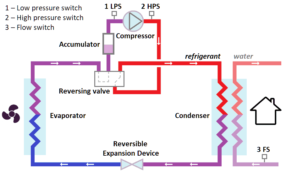
Reversible Expansion Device: Regulates refrigerant flow in both directions.
Reversing Valve: Switches refrigerant flow for heating, cooling, or defrosting.
Accumulator: Prevents liquid refrigerant from damaging the compressor.
Low-Pressure Switch: Stops the compressor to prevent freezing at low pressure.
High-Pressure Switch: Protects the system from excessive pressure.
Flow Switch: Ensures proper water flow to safeguard the heat exchanger.
(click to read more about conversion)
Key Components for Conversion
Split systems, which separate indoor and outdoor units, are the easiest to convert due to their modular design. A reversing valve is added during conversion to enable the refrigerant flow to reverse, allowing the system to switch between heating and cooling modes. This feature also facilitates defrosting during winter operation.
Many split-system air conditioners use components such as compressors and coils that are identical to those in heat pumps manufactured by the same brand. This overlap simplifies conversion. In some cases, the cooling function is disabled, and the indoor wall unit is replaced with a condenser designed for heating.
Efficiency and Compressor Type
Converted air conditioners typically have a lower Coefficient of Performance (COP) compared to dedicated heat pumps. This is because air conditioners are engineered primarily for cooling, with compressors optimized for a limited temperature and pressure range.
When operating in heating mode, the outdoor coil must extract heat from ambient air, a task it is not designed to perform efficiently. This can result in reduced heating performance, especially in colder climates.
Compressor Types:
- Rotary Compressors: Generally less efficient in heating mode.
- Scroll Compressors: Offer higher heating performance due to better pressure handling.
- Inverter Compressors: Improve overall system efficiency by modulating output to match heating or cooling demand.
Refrigerant Compatibility
Air conditioners often use refrigerants that are optimized for cooling but less effective at absorbing heat in low-temperature conditions. Switching to a refrigerant better suited for heat pump operation can enhance performance but typically requires significant system modifications.
Essential Components for Heat Pump Operation
- Operating Unit (Controller): Automates defrost cycles, regulates compressor performance, and manages safety by integrating flow, temperature, and pressure sensors.
- Accumulator: Protects the compressor by ensuring that only vapor enters, preventing damage from liquid refrigerant returning from the outdoor coil during heating.
- Check Valves: Essential when using thermostatic expansion valves (TXVs) to maintain correct refrigerant flow direction for both heating and cooling.
- Safety Switches: If the air conditioner lacks high-pressure and low-pressure safety switches, these must be added or adjusted to protect the system from potential damage during operation.
- Metering Devices: Option A: A bi-directional metering device that regulates refrigerant flow in both directions. Option B: TXVs combined with check valves for precise flow control. Standard air conditioners typically lack this feature, necessitating upgrades for effective heat pump operation.
Condenser for heat pump
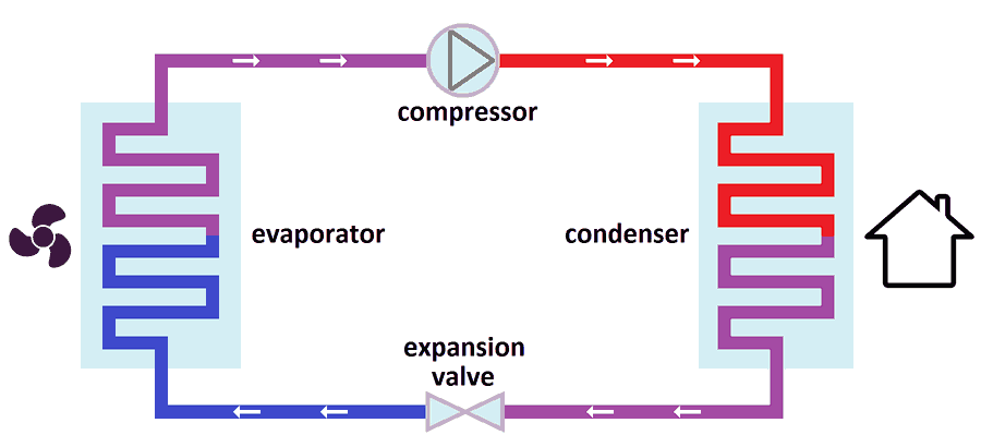
The condenser functions as the heat exchanger on the secondary circuit of a heat pump. It transfers heat from the hot refrigerant to the heating water. The refrigerant enters the condenser in a vapor phase and undergoes cooling, condensation, and subcooling. The majority of the heat transferred to the heating water comes from the latent heat of condensation.
Below is a list of commonly used plate heat exchangers serving as condensers for heat pumps:
- SWEP B8LASH: For capacities of 3–10 kW, this asymmetric exchanger features combo 3/4".
- SWEP B26H / B26FH: Asymmetric design suitable for 5–20 kW heat pumps, with soldering connections for the primary circuit and ISO G 1" external thread for the secondary circuit.
- SWEP B25TH / B85H / B86H: Used for capacities of 10–50 kW (e.g., in air conditioning). Connections are combo 1" or combo 1 1/4".
- SWEP B18H, B185H, B16DW: Designed for natural refrigerants like CO2
 , with pressure ratings up to 140 bar. Connections can be customized.
Asymmetric exchanger
Asymmetric designs feature narrower internal channels for refrigerant, optimizing heat transfer where water flow rates are approximately 10 times higher than refrigerant flow rates. This design ensures efficient operation in air conditioning and heat pumps.
Key Features of SWEP Exchangers
- SWEP B25TH: Popular for its pure solder connections on the refrigerant side, making it a favorite among technicians.
- SWEP B85H / B86H: Provide higher efficiency than the B25TH. These exchangers feature combo connections (external thread with inner pipe for soldering). The B86H offers the highest efficiency but also exhibits higher pressure losses, which can be mitigated by increasing the number of plates.
- Connection Material: All SWEP heat exchangers are equipped with stainless steel connections, requiring silver solder with at least 45 % silver content for proper sealing.
Heat exchangers for heat pumps
The following table outlines condensers used in heat pumps, showing the pressure losses in the water circuit. These calculations assume R410A refrigerant on the primary side and water temperature gradient on the secondary side.
| Capacity | Exchanger type | Pressure drop |
|---|---|---|
| 5 kW | B26FHx18 | 4 kPa |
| 10 kW | B26Hx24 | 9 kPa |
| 15 kW | B26Hx40 | 8 kPa |
| 20 kW | B85Hx50 | 17 kPa |
| 30 kW | B85Hx70 | 20 kPa |
Design Pressure of the Exchanger
The design pressure of a heat exchanger can be determined from the graph included in its product sheet. Typical design pressures for commonly used exchangers are approximately:
- 46 bar(g) at 75 °C for B8TH, B8LASH;
- 48 bar(g) at 75 °C for B26H, B26FH;
- 46 bar(g) at 75 °C for B25TH;
- 50 bar(g) at 75 °C for B85H, B86H.
Pressure-temperature charts
Pressure-temperature charts for individual refrigerants are widely available online. For reference, a summary of refrigerant pressures in bar(g) is provided in the table below (source: A-GAS):
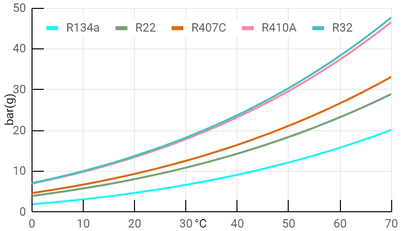
R22, R32, R410A, R407C, R134a Pressure-Temperature Chart.
| R22 bar(g) | R22 psig | |
|---|---|---|
| -40 °C | 0.03 | 0.4 |
| -38 °C | 0.15 | 2.1 |
| -36 °C | 0.25 | 3.6 |
| -34 °C | 0.36 | 5.3 |
| -32 °C | 0.49 | 7.1 |
| -30 °C | 0.62 | 9.1 |
| -28 °C | 0.77 | 11.1 |
| -26 °C | 0.92 | 13.4 |
| -24 °C | 1.08 | 15.7 |
| -22 °C | 1.26 | 18.2 |
| -20 °C | 1.44 | 20.9 |
| -18 °C | 1.63 | 23.7 |
| -16 °C | 1.84 | 26.7 |
| -14 °C | 2.06 | 29.9 |
| -12 °C | 2.29 | 33.2 |
| -10 °C | 2.54 | 36.8 |
| -8 °C | 2.79 | 40.5 |
| -6 °C | 3.06 | 44.4 |
| -4 °C | 3.35 | 48.6 |
| -2 °C | 3.65 | 52.9 |
| 0 °C | 3.97 | 57.5 |
| 2 °C | 4.30 | 62.3 |
| 4 °C | 4.65 | 67.4 |
| 6 °C | 5.0 | 72.7 |
| 8 °C | 5.4 | 78.2 |
| 10 °C | 5.8 | 84.1 |
| 12 °C | 6.2 | 90.1 |
| 14 °C | 6.7 | 96.5 |
| 16 °C | 7.1 | 103 |
| 18 °C | 7.6 | 110 |
| 20 °C | 8.1 | 117 |
| 22 °C | 8.6 | 125 |
| 24 °C | 9.1 | 133 |
| 26 °C | 9.7 | 141 |
| 28 °C | 10.3 | 149 |
| 30 °C | 10.9 | 158 |
| 32 °C | 11.5 | 167 |
| 34 °C | 12.2 | 177 |
| 36 °C | 12.9 | 187 |
| 38 °C | 13.6 | 197 |
| 40 °C | 14.3 | 208 |
| 42 °C | 15.1 | 219 |
| 44 °C | 15.9 | 230 |
| 46 °C | 16.7 | 242 |
| 48 °C | 17.5 | 254 |
| 50 °C | 18.4 | 267 |
| 52 °C | 19.3 | 280 |
| 54 °C | 20.3 | 294 |
| 56 °C | 21.2 | 308 |
| 58 °C | 22.2 | 322 |
| 60 °C | 23.3 | 337 |
| 62 °C | 24.3 | 353 |
| 64 °C | 25.4 | 369 |
| 66 °C | 26.6 | 385 |
| 68 °C | 27.7 | 402 |
| 70 °C | 28.9 | 420 |
| (click to expand other rows) | ||
Note: The pressure bar(g) refers to the pressure relative to atmospheric pressure (excess pressure above 1 bar in ambient air).
Some refrigerants, such as R407C, are blends of multiple refrigerants, each with distinct condensing temperatures. As a result, two temperatures are specified for these refrigerants:
- Boiling Temperature: The point at which liquid refrigerant begins to boil and transitions into vapor.
- Condensing Temperature: The point at which vapor refrigerant begins to condense back into liquid.
Heat Pump Freezing and Heat Exchanger Failure
Exchanger rupture typically occurs due to one of the following reasons:
- Operating Pressure Exceeding Design Limits. If the refrigerant pressure exceeds the heat exchanger's design pressure, the system can fail. To prevent this, a high-pressure switch is essential. It automatically shuts off the compressor when the operating pressure surpasses safe limits (e.g., due to system faults).
- Freezing of the Heat Exchanger. Freezing is a common risk during reverse operation (defrost mode) or startup. Reverse operation is activated for a few minutes to defrost the evaporator, during which the refrigerant temperature can drop to as low as -20 °C. This poses a risk of freezing the water inside the condenser. Even if the outlet water temperature is 3 °C, localized areas inside the heat exchanger can fall below freezing, leading to potential damage.

Preventive Measures Against Freezing
To mitigate the risk of freezing and ensure reliable heat pump operation, the following measures can be implemented:
- Temperature Sensors: Install a temperature sensor at the water outlet of the heat exchanger. If the outlet temperature drops below a set threshold, the compressor is automatically turned off.
- Antifreeze and Electric Heating: Use antifreeze additives or an electric heating element on the heat exchanger during reverse operation to prevent freezing.
- Flow Switch: Ensure full water flow on the secondary (water) side by maintaining constant circulation pump speed. Radiator valves should remain open to allow uninterrupted flow.
- Strainer: Install a strainer at the water inlet to capture particles larger than 1 mm. Blockages caused by debris can reduce flow and increase the risk of freezing.
- Pump Operation Delays: Allow the water pump to continue running for several minutes after the compressor stops. Similarly, start the water pump before activating the compressor to maintain consistent flow.
- Fan Management During Defrost: Stop the fan during defrost cycles to increase the evaporator's temperature and prevent excessive cooling.
- Low-Capacity Compressor Start: Begin compressor operation at the lowest capacity to minimize the drop in evaporation temperature during startup.
Challenges with Converted Air Conditioners
Air conditioning units, designed primarily for summer operation, often have smaller gaps between the fins on the outdoor unit compared to dedicated heat pumps. When modified into a heat pump, these units are more prone to frost buildup, which can lead to operational challenges.
SWEP B26FH Heat Exchanger for Heat Pumps
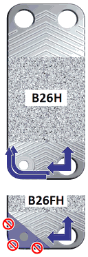
To address freezing risks, SWEP offers a specialized version of its commonly used B26H heat exchanger for refrigerants. The modified B26FH version eliminates channels in the corner near the refrigerant inlet, a location particularly susceptible to freezing. This design innovation significantly reduces the risk of exchanger damage and improves overall heat pump reliability.
Consequences of Freezing
Freezing water inside the heat exchanger can lead to severe damage, including ruptures that may compromise the entire heat pump. In extreme cases, water can enter the refrigerant circuit, causing irreversible system failure. Implementing the measures outlined above helps minimize these risks
Evaporator for Heat Pumps
The evaporator is the heat exchanger located on the primary circuit of a heat pump. Within this exchanger, the cold liquid refrigerant evaporates. The system operates such that the expansion valve preceding the evaporator reduces the refrigerant pressure, thereby lowering its boiling temperature. Typically, the refrigerant temperature in the evaporator is set to approximately 0 °C, though it may be lower depending on the application.
To evaporate, the refrigerant absorbs heat, which is typically sourced from the environment, such as ambient air or the ground. This energy, stored in the phase change during evaporation, is later transferred to the heating water in the condenser. The majority of the energy transferred from the environment to the refrigerant is stored in this state change.
Plate Heat Exchangers for Small Applications
For small-scale heat pump applications, SWEP plate heat exchangers are commonly used as evaporators. For optimal performance:
- The refrigerant inlet connection should always be smaller than or equal to the outlet connection to maintain appropriate flow dynamics.
- Ensure refrigerant velocities of 10–25 m/s at the inlet and 5–10 m/s at the outlet (2.5–5 m/s for horizontal connections). This prevents oil accumulation in the heat exchanger, which can compromise efficiency and reliability.
High-Performance Heat Pump Evaporators
For high-capacity systems, additional plates are required in the heat exchanger to meet performance demands. If more than 30 plates are needed, a specialized plate heat exchanger (with distribution system) is usually recommended, such as those from the V-series, P-series, F-series, Q-series, or other types.
Heat Exchangers with Distribution systems: These are equipped with a distribution system that ensures even refrigerant flow across all plates, preventing uneven flow where refrigerant might otherwise pass only through plates near the inlet. Examples include V25 and V80. This design avoids freezing and maintains efficiency.
Without a proper distribution system, larger plate heat exchangers may suffer from inefficiency and freezing risks due to uneven refrigerant flow. Importantly, the distribution system does not hinder performance if the heat exchanger is also used as a condenser.

Separation Exchanger for Heat Pumps
A separation exchanger is commonly used to isolate the antifreeze circuit from the heating water circuit. This allows the use of glycol-based mixtures in the external circuit (e.g., for outdoor use) while maintaining pure heating water in the indoor circuit. Additionally, separation exchangers can be utilized to protect the heat pump from exposure to dirty or aggressive media, ensuring system longevity and reliability.
To maintain the efficiency of the heat pump, it is crucial to minimize the temperature difference between the two circuits. Care must be taken to manage flow rates, as pressure losses increase proportionally to the square of the flow rate.
| Flow rate | Exchanger type | Pressure loss |
|---|---|---|
| 1 m3/h | E8THx20 B85Hx20 XB06H-1-30 |
10 kPa |
| 2 m3/h | E8THx40 B85Hx40 XB12H-1-40 XB37M-1-26 XB37H-1-36 |
13 kPa |
| 3 m3/h | B28Hx36 B85Hx50 XB12H-1-50 XB37M-1-36 XB37H-1-50 |
16 kPa |
| 5 m3/h | B28Hx56 B85Hx70 XB12H-1-80 XB37M-1-60 XB37H-1-80 |
20 kPa |
| 10 m3/h | B28Hx116 B85Hx140 |
25 kPa |
Pohraniční 1280/112
703 00 Ostrava-Vítkovice
Czech Republic
| L | +44 74 9187 2667 |
| E | +44 74 9187 2667 |
| B | info@heat-exchangers.uk |
| sales@heat-exchangers.uk |


